OBJECTIVE:
- speed variation
- Digital display
of Potentiometre
- LCD display(duty cycle %)
- How to work with function
COMPONENTS:
- Potentiometre
- 2 CAp (22pic)
- 1 quartz (4MHZ)
- pic 16F877A
- Motor
- L293D
- LCD 16*2
Definition :
PWM (Pulse
Width Modulation) is a method of generating signal shown above.
In short, PWM allows easy control the amount of power provided to external device e.g. motor or LED. When frequency of the signal is changed in time it can be used to generate sound.
In short, PWM allows easy control the amount of power provided to external device e.g. motor or LED. When frequency of the signal is changed in time it can be used to generate sound.
 |
| motor animated |
 |
| Led animated |
Discription:
PWM Mode (PWM) In Pulse Width
Modulation mode, the CCPx pin produces up to a 10-bit resolution PWM
output. Since the CCP1 pin is multiplexed with the PORTC data latch, the
TRISC<2> bit must be cleared to make the CCP1 pin an output
A PWM output has a time
base (period) and a time that the output stays high (duty cycle). The
frequency of the PWM is the inverse of the period (1/period).

The PWM period is specified by
writing to the PR2 register. The PWM period can be calculated using the
following formula:
Period = [(PR2) + 1] • 4 • TOSC •
(TMR2 Prescale Value)
PWM frequency is defined as 1/[ period]
PWM DUTY CYCLE:
Duty Cycle =(CCPR1L:CCP1CON<5:4>) •
TOSC • (TMR2 Prescale Value)
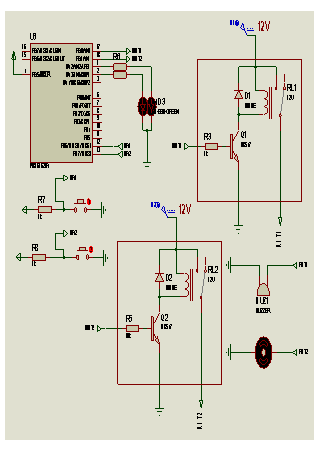
CIRCUIT DIAGRAM:

Video: